- 您现在的位置:买卖IC网 > Sheet目录1990 > CDCR83DBQG4 (Texas Instruments)IC DIRECT RAMBUS CLK GEN 24-QSOP

CDCR83
DIRECT RAMBUS CLOCK GENERATOR
SCAS632B APRIL 2001 REVISED OCTOBER 2005
8
POST OFFICE BOX 655303
DALLAS, TEXAS 75265
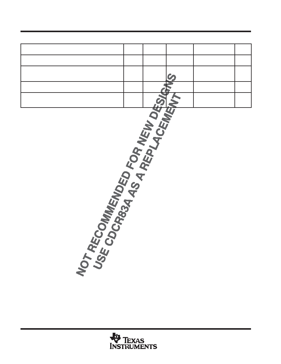
state transition latency specifications (continued)
PARAMETER
FROM
TO
TEST
CONDITIONS
MIN
TYP
MAX
UNIT
t(powerdown)
Delay time, PWRDNB
↓ to the device in the
power-down mode
Normal
Powerdown
See Figure 8
1
ms
t(STOP)
Maximum time in CLKSTOP (STOPB = 0)
before reentering normal mode
(STOPB = 1)
STOPB
Normal
See Figure 10
100
s
t(ON)
Minimum time in normal mode (STOPB = 1)
before reentering CLKSTOP (STOPB = 0)
Normal
CLK stop
See Figure 10
100
ms
t(DISTLOCK)
Time from when CLK/CLKB output is
settled to when the phase error between
SYNCLKN and PCLKM falls within t(phase)
Unlocked
Locked
5
ms
All typical values are at VDD = 3.3 V, TA = 25°C.
发布紧急采购,3分钟左右您将得到回复。
相关PDF资料
CDP68HC68T1M
IC RTC 32X8 NVSRAM CMOS 20-SOIC
CPLL66-1600-2200
IC VCO PLL/SYNTH 2.2GHZ SMD
CPLL66-2175-2175
IC VCO PLL/SYNTH 2175MHZ SMD
CPLL66-2400-2500
IC VCO PLL/SYNTH 2500MHZ SMD
CPLL66-2450-2450
IC VCO PLL/SYNTH 2450MHZ SMD
CPLL66-3160-3380
IC VCO PLL/SYNTH 3380MHZ SMD
CPLL66-3475-3475
IC VCO PLL/SYNTH 3475MHZ SMD
CPLL66-4160-4380
IC VCO PLL/SYNTH 4380MHZ SMD
相关代理商/技术参数
CDCR83DBQR
功能描述:时钟发生器及支持产品 400MHz Direct Rambus (TM) Clock Gen RoHS:否 制造商:Silicon Labs 类型:Clock Generators 最大输入频率:14.318 MHz 最大输出频率:166 MHz 输出端数量:16 占空比 - 最大:55 % 工作电源电压:3.3 V 工作电源电流:1 mA 最大工作温度:+ 85 C 安装风格:SMD/SMT 封装 / 箱体:QFN-56
CDCR83DBQRG4
功能描述:时钟发生器及支持产品 400MHz Direct Rambus (TM) Clock Gen RoHS:否 制造商:Silicon Labs 类型:Clock Generators 最大输入频率:14.318 MHz 最大输出频率:166 MHz 输出端数量:16 占空比 - 最大:55 % 工作电源电压:3.3 V 工作电源电流:1 mA 最大工作温度:+ 85 C 安装风格:SMD/SMT 封装 / 箱体:QFN-56
CDCS501
制造商:TI 制造商全称:Texas Instruments 功能描述:SSC Clock Generator/Buffer
CDCS501PW
功能描述:时钟发生器及支持产品 Clock Driver w/ Opt Spread-Spect Clock RoHS:否 制造商:Silicon Labs 类型:Clock Generators 最大输入频率:14.318 MHz 最大输出频率:166 MHz 输出端数量:16 占空比 - 最大:55 % 工作电源电压:3.3 V 工作电源电流:1 mA 最大工作温度:+ 85 C 安装风格:SMD/SMT 封装 / 箱体:QFN-56
CDCS501PW
制造商:Texas Instruments 功能描述:Clock IC
CDCS501PWR
功能描述:时钟发生器及支持产品 Clock Driver w/ Opt Spread-Spect Clock RoHS:否 制造商:Silicon Labs 类型:Clock Generators 最大输入频率:14.318 MHz 最大输出频率:166 MHz 输出端数量:16 占空比 - 最大:55 % 工作电源电压:3.3 V 工作电源电流:1 mA 最大工作温度:+ 85 C 安装风格:SMD/SMT 封装 / 箱体:QFN-56
CDCS502
制造商:TI 制造商全称:Texas Instruments 功能描述:Crystal Oscillator / Clock Generator with optional SSC
CDCS502_12
制造商:TI 制造商全称:Texas Instruments 功能描述:Crystal Oscillator / Clock Generator with optional SSC